Modbus TCP
Warning
The Modbus functionality is under development and may be subject to change. Note that Modbus features are only supported from version 0.27.0.
Overview
Evolabel printers provide a Modbus TCP Server interface which can be accessed on port 502. Only one client connection at a time is allowed. All Modbus addresses in this documentation are 1-based, and offsets are 0-based from their respective register bank.
Supported Function Codes
- FC 1 Read Discrete Output Coils
- The output coil registers 00001-00004 can be read using a single Modbus transaction.
- FC 2 Read Discrete Input Contacts
- The discrete input registers 10001-10006 can be read using a single Modbus transaction.
- FC 3 Read Multiple Holding Registers
- It is only supported to read one register at a time. Most holding registers map to unique function calls that are not useful to group together in a single transaction.
- FC 4 Read Input Registers
- The modbus registers 30001-30080 can be read using a single Modbus transaction.
- FC 5 Write Single Discrete Output Coil
- Set the state of a single hardware output port.
- FC 6 Write Single Register
- Trigger a function call.
- FC 15 Write Multiple Discrete Output Coils
- Set the state of multiple hardware output ports 00001-00006 in a single transaction.
- FC 16 Write Multiple Registers
- It is only supported to write one register at a time. Most holding registers map to unique function calls that are not useful to group together in a single transaction.
Discrete Output Coils
| Address | Name | Description |
|---|---|---|
| 00001 | RW_IO_O1 | Read/Write state of O1 |
| 00002 | RW_IO_O2 | Read/Write state of O2 |
| 00003 | RW_IO_O3 | Read/Write state of O3 |
| 00004 | RW_IO_O4 | Read/Write state of O4 |
Discrete Input Contacts
| Address | Name | Description |
|---|---|---|
| 10001 | RD_IO_IN1 | Read state of IN1 |
| 10002 | RD_IO_IN2 | Read state of IN2 |
| 10003 | RD_IO_IN3 | Read state of IN3 |
| 10004 | RD_IO_IN4 | Read state of IN4 |
| 10005 | RD_IO_TRIG1 | Read state of TRIG1 |
| 10006 | RD_IO_TRIG2 | Read state of TRIG2 |
Input Registers
| Address | Name | Description |
|---|---|---|
| 30001 | RD_MARKER_STATE | Current state of the marker |
| 30005 | RD_SEQUENCE_STATE | Read current sequence state |
| 30008 | RD_SEQUENCE_RESULT | Read last finished sequence result |
| 30010 | RD_APPLICATOR_STATE | Current state of the applicator |
| 30015 | RD_PRINTER_STATE | Current state of the printer |
| 30020 | RD_MESSAGES_ALARMS | Read currently active alarms |
| 30021 | RD_MESSAGES_WARNINGS | Read currently active warnings |
| 30025 | RD_JOB_STATE | Get job availability |
| 30031 | RD_STAND1_POS | Stand 1 position in mm |
| 30032 | RD_STAND2_POS | Stand 2 position in mm |
| 30033 | RD_STAND3_POS | Stand 3 position in mm |
| 30041 | RD_SCANNER1_RESULT | Scanner 1 read data (32 registers, 64 ASCII characters) |
| 30081 | RD_SCANNER2_RESULT | Scanner 2 read data (32 registers, 64 ASCII characters) |
| 30121 | RD_SCANNER3_RESULT | Scanner 3 read data (32 registers, 64 ASCII characters) |
Holding Registers
| Address | Name | Description |
|---|---|---|
| 40001 | WR_MARKER_STATE | Set the printer online or offline |
| 40002 | WR_API_HEARTBEAT_TIMEOUT | Require WR_API_HEARTBEAT |
| 40003 | WR_API_HEARTBEAT | Ensure printer that Modbus client is alive |
| 40005 | WR_SEQUENCE_PRINT | Print active job immediately |
| 40006 | WR_SEQUENCE_APPLY | Apply label with specified apply sequence |
| 40007 | WR_SEQUENCE_ABORT | Abort the current product sequence |
| 40008 | WR_SEQUENCE_FINISH | Indicate that current product sequence is finished |
| 40020 | WR_MESSAGES_RESET | Reset active alarms |
| 40021 | WR_MESSAGE1 | Set custom message 1 |
| 40022 | WR_MESSAGE2 | Set custom message 2 |
| 40025 | WR_JOB_CLEAR | Clear all jobs |
| 40030 | WR_STAND_STOP | Stop specified stands |
| 40031 | WR_STAND1_GOTO_MM | Goto stand position in mm |
| 40032 | WR_STAND2_GOTO_MM | Goto stand position in mm |
| 40033 | WR_STAND3_GOTO_MM | Goto stand position in mm |
| 40034 | WR_STAND1_GOTO_STORED_POS | Goto stored position |
| 40035 | WR_STAND2_GOTO_STORED_POS | Goto stored position |
| 40036 | WR_STAND3_GOTO_STORED_POS | Goto stored position |
Motorized Stands
Motorized Stands are controlled by addressing a stand number. The stand number is shown in the user interface under Peripherals -> Motorized Stand.
Discrete Output Coils
The state of hardware output ports can be read and set by reading and writing to the corresponding address.
RW_IO_O1
| Description | Address | Offset |
|---|---|---|
| Read/Write state of O1 | 00001 | 0x00 |
| Value | Description |
|---|---|
0 |
Inactive |
1 |
Active |
RW_IO_O2
| Description | Address | Offset |
|---|---|---|
| Read/Write state of O2 | 00002 | 0x01 |
| Value | Description |
|---|---|
0 |
Inactive |
1 |
Active |
RW_IO_O3
| Description | Address | Offset |
|---|---|---|
| Read/Write state of O3 | 00003 | 0x02 |
| Value | Description |
|---|---|
0 |
Inactive |
1 |
Active |
RW_IO_O4
| Description | Address | Offset |
|---|---|---|
| Read/Write state of O4 | 00004 | 0x03 |
| Value | Description |
|---|---|
0 |
Inactive |
1 |
Active |
Discrete Inputs
The state of hardware input ports can be read by reading the corresponding address.
RD_IO_IN1
| Description | Address | Offset |
|---|---|---|
| Read state of IN1 | 10001 | 0x00 |
| Value | Description |
|---|---|
0 |
Inactive |
1 |
Active |
RD_IO_IN2
| Description | Address | Offset |
|---|---|---|
| Read state of IN2 | 10002 | 0x01 |
| Value | Description |
|---|---|
0 |
Inactive |
1 |
Active |
RD_IO_IN3
| Description | Address | Offset |
|---|---|---|
| Read state of IN3 | 10003 | 0x02 |
| Value | Description |
|---|---|
0 |
Inactive |
1 |
Active |
RD_IO_IN4
| Description | Address | Offset |
|---|---|---|
| Read state of IN4 | 10004 | 0x03 |
| Value | Description |
|---|---|
0 |
Inactive |
1 |
Active |
RD_IO_TRIG1
| Description | Address | Offset |
|---|---|---|
| Read state of TRIG1 | 10005 | 0x04 |
| Value | Description |
|---|---|
0 |
Inactive |
1 |
Active |
RD_IO_TRIG2
| Description | Address | Offset |
|---|---|---|
| Read state of TRIG2 | 10006 | 0x05 |
| Value | Description |
|---|---|
0 |
Inactive |
1 |
Active |
Input Registers
RD_MARKER_STATE
| Description | Address | Offset |
|---|---|---|
| Current state of the marker | 30001 | 0x00 |
| Value | Description |
|---|---|
0b0000000000000001 (1) |
Offline |
0b0000000000000010 (2) |
Online |
0b0000000000000110 (6) |
Stopping |
0b0000000000001001 (9) |
Alarm |
0b0000000000010000 (16) |
Test |
0b1000000000000000 (32768) |
Stand Position Changed |
The lower bits of the register holds
the current marker state. This is a bitfield where each bit indicates
one of the states "offline", "online", "stopping", "alarm"
and "test".
Note that "stopping" is a substate to "online" and
"alarm" is a substate to "offline". Those states will have
the bit representing their superstate set as well.
The upper bits are used for indicating state changes and that more information can be read in other registers. The upper bits are cleared on read.
b15: Updated information in any of RD_STAND1_POS, RD_STAND2_POS, or RD_STAND3_POS
RD_SEQUENCE_STATE
| Description | Address | Offset |
|---|---|---|
| Read current sequence state | 30005 | 0x04 |
| Value | Description |
|---|---|
0b0000000000000000 (0) |
idle |
0b0000000000000001 (1) |
printing |
0b0000000000000010 (2) |
wait_apply |
0b0000000000000011 (3) |
applying |
0b0000000000000100 (4) |
ok_wait_next |
0b0000000000001000 (8) |
error_wait_resume |
0b0000000000001111 (15) |
State mask |
0b0000000011110000 (240) |
Label index mask |
Get the current print and apply sequence state. This is useful for high level tracking of print and apply sequences.
The register is divided into two parts: state, and label index.
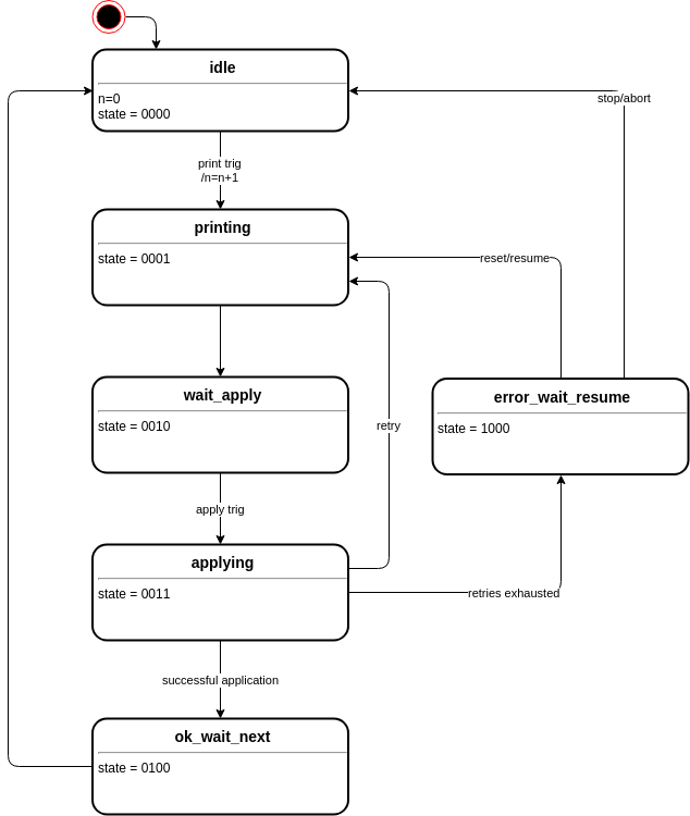
Note
Some states are transient (will only be active during a very brief time), so a PLC program must handle that e.g. after printing, the next state wait_apply is never read, but the state will transfer directly to applying, as shown in the examples below.
Example: Triggering a single label print and apply cycle with a normal sequential sequence
Example: Triggering a dual label print and apply cycle with a normal sequential sequence
Example: Externally controlled print and apply cycle
RD_SEQUENCE_RESULT
| Description | Address | Offset |
|---|---|---|
| Read last finished sequence result | 30008 | 0x07 |
| Value | Description |
|---|---|
0b0000000000000001 (1) |
Success |
0b0100000000000000 (16384) |
Data valid |
0b1000000000000000 (32768) |
Data loss |
Read the result of the last finished sequence (either successfully finished, or aborted).
b0 contains the result when b14 is 1.
- Success
- When Data valid is set, this bit represents the success of the last sequence. Automatically cleared upon read.
- Data valid
- Set when a sequence is finished or aborted. Automatically cleared upon read.
- Data loss
- Unread data was overwritten by new state changes. Automatically cleared upon read.
Example: One successful sequence followed by one failed sequence (where state is from RD_SEQUENCE_STATE).
RD_APPLICATOR_STATE
| Description | Address | Offset |
|---|---|---|
| Current state of the applicator | 30010 | 0x09 |
| Value | Description |
|---|---|
0b0000000000000001 (1) |
Nonblocking |
0b0000000000000010 (2) |
Applying |
0b0000000000010000 (16) |
Applicator Error |
0b1000000000000000 (32768) |
Data loss |
Get the current applicator state. This is valid both for test sequences and production sequences. Each bit represents one state, and multiple bits can be set simultaneously.
- Nonblocking
- The applicator is in a position that will not block products in front of it. This may
include printing or service positions, and will always be
1for some applicator types that never block. - Applying
- The applicator is applying. Note that this state may be very short and can cause data loss for fast applicators.
- Error
- The applicator is in an error state.
- Data loss
- Unread data was overwritten by new state changes.
RD_PRINTER_STATE
| Description | Address | Offset |
|---|---|---|
| Current state of the printer | 30015 | 0x0E |
| Value | Description |
|---|---|
0b0000000000000001 (1) |
Label stabilizing |
0b0000000000000010 (2) |
Print sequence is active |
0b0000000000000100 (4) |
No print data |
0b0000000000001000 (8) |
Trig blocking |
0b0000000000010000 (16) |
Printer alarm |
0b0000000000100000 (32) |
Soft inhibition |
0b0000000001000000 (64) |
Applicator is active |
Get the current printer state. This is valid both for test sequences and production sequences. Each bit represents one aspect, and multiple bits can be set simultaneously.
Note
A printout can only be started if all bits in this register is zero.
- Label stabilizing
- The label is printed but waits for mechanical stabilization before application can start. This is a transient state that is only active up to 200 ms.
- Print sequence is active
- Printer is printing, waiting for application to start, or backfeeding.
- No print data
- No print data is loaded to the printhead. If the printer is in Dispenser Mode this bit is never set.
- Trig blocking
- Trig block timer is active.
- Printer alarm
Print head open, paper out, or ribbon out.
New in version Unreleased.
- Soft inhibition
- A software inhibition is active.
- Applicator is active
- Applicator is blocking printouts.
RD_MESSAGES_ALARMS
| Description | Address | Offset |
|---|---|---|
| Read currently active alarms | 30020 | 0x13 |
| Value | Description |
|---|---|
0b0000000000000001 (1) |
low_air_pressure_alarm |
0b0000000000000010 (2) |
paper_out |
0b0000000000000100 (4) |
ribbon_out |
0b0000000000001000 (8) |
printhead_open |
0b0000000000010000 (16) |
applicator |
0b0000000000100000 (32) |
product_failed |
0b0000000001000000 (64) |
pivotable_stand_alarm |
0b1000000000000000 (32768) |
any |
Get active alarms. The lower bits are mapped to specific alarms or alarm groups. The highest bit (b15) is set whenever any alarm, including ones not represented by the lower bits, is active.
The description in the table below is the exact alarm name, as would have been reported as “message_id” in messages.active.changed , with the exception of b4 (which represents any alarm in the group “applicator”) and b15.
RD_MESSAGES_WARNINGS
| Description | Address | Offset |
|---|---|---|
| Read currently active warnings | 30021 | 0x14 |
| Value | Description |
|---|---|
0b0000000000000001 (1) |
low_air_pressure_warning |
0b0000000000000010 (2) |
paper_low |
0b0000000000000100 (4) |
ribbon_low |
0b0000000000010000 (16) |
applicator |
0b1000000000000000 (32768) |
any |
Get active warnings. The register works similar to RD_MESSAGES_ALARMS.
RD_JOB_STATE
| Description | Address | Offset |
|---|---|---|
| Get job availability | 30025 | 0x18 |
| Value | Description |
|---|---|
0b0000000000000000 (0) |
No job |
0b0000000000000001 (1) |
Job available |
0b0000000000000011 (3) |
Ready to Print |
Get job availability. API documentation: jobs.state.get
RD_STAND1_POS
| Description | Address | Offset |
|---|---|---|
| Stand 1 position in mm | 30031 | 0x1E |
| Value | Description |
|---|---|
0b0000011111111111 (2047) |
Position Mask |
0b0000100000000000 (2048) |
Sign. 0 means positive. 1 means negative. |
0b1000000000000000 (32768) |
Unknown Position |
This register contains the last known position for the first motorized stand.
If b15 is 1 the position is unknown.
If b15 is 0, b10-b0 contains the stand position in mm in user coordinates.
b11 specifies the sign of the position value. 0 means positive, and 1 means negative.
RD_STAND2_POS
| Description | Address | Offset |
|---|---|---|
| Stand 2 position in mm | 30032 | 0x1F |
| Value | Description |
|---|---|
0b0000011111111111 (2047) |
Position Mask |
0b0000100000000000 (2048) |
Sign. 0 means positive. 1 means negative. |
0b1000000000000000 (32768) |
Unknown Position |
This register contains the last known position for the second motorized stand.
For details, see RD_STAND1_POS.
RD_STAND3_POS
| Description | Address | Offset |
|---|---|---|
| Stand 3 position in mm | 30033 | 0x20 |
| Value | Description |
|---|---|
0b0000011111111111 (2047) |
Position Mask |
0b0000100000000000 (2048) |
Sign. 0 means positive. 1 means negative. |
0b1000000000000000 (32768) |
Unknown Position |
This register contains the last known position for the third motorized stand.
For details, see RD_STAND1_POS.
RD_SCANNER1_RESULT
Warning
Implementation is in beta state.
| Description | Address | Offset |
|---|---|---|
| Scanner 1 read data (32 registers, 64 ASCII characters) | 30041 | 0x28 - 0x47 |
These registers contain the scanner data from scanner 1.
Each register (16 bits) is interpreted as two ASCII characters.
The data is truncated if it is longer that 64 characters. If shorter it is padded with 0x00.
If the last status from the scanner is not "ok", the data will be the empty string (all 0x00).
RD_SCANNER2_RESULT
Warning
Implementation is in beta state.
| Description | Address | Offset |
|---|---|---|
| Scanner 2 read data (32 registers, 64 ASCII characters) | 30081 | 0x50 - 0x6F |
These registers contain the scanner data from scanner 2.
For details, see RD_SCANNER1_RESULT.
RD_SCANNER3_RESULT
Warning
Implementation is in beta state.
| Description | Address | Offset |
|---|---|---|
| Scanner 3 read data (32 registers, 64 ASCII characters) | 30121 | 0x78 - 0x97 |
These registers contain the scanner data from scanner 3.
For details, see RD_SCANNER1_RESULT.
Holding Registers
Complex commands with parameters or options are issued by writing a 16 bit value to the corresponding address.
WR_MARKER_STATE
| Description | Address | Offset |
|---|---|---|
| Set the printer online or offline | 40001 | 0x00 |
| Value | Description |
|---|---|
0b0000000000000000 (0) |
Offline |
0b0000000000000001 (1) |
Online |
Instruct the printer to go either offline or online.
WR_API_HEARTBEAT_TIMEOUT
| Description | Address | Offset |
|---|---|---|
| Require WR_API_HEARTBEAT | 40002 | 0x01 |
If client writes any value but 0 to this register,
WR_API_HEARTBEAT must be written
to at least every N seconds, where N is the value written to
this register. If the client disconnects or WR_API_HEARTBEAT is not written to at least every N
seconds, the printer will enter alarm state.
Set to 0 (default) to toggle off. Maximum accepted value is
10.
This setting is transient. If the client disconnects, or fails to
send WR_ALIVE in time so that an
alarm is raised, the value is reset to 0 and will have to be
set again.
If any non 0 value has been written, a client must write 0
to this register again before disconnecting to avoid raising an
alarm.
WR_API_HEARTBEAT
| Description | Address | Offset |
|---|---|---|
| Ensure printer that Modbus client is alive | 40003 | 0x02 |
Inform printer that the client is still alive. This is needed when
WR_API_HEARTBEAT_TIMEOUT
has been set to anything but 0.
WR_SEQUENCE_PRINT
| Description | Address | Offset |
|---|---|---|
| Print active job immediately | 40005 | 0x04 |
| Value | Description |
|---|---|
0b0000000000000000 (0) |
|
0b0000000000000001 (1) |
Print and Apply sequence 1 |
0b0000000000000010 (2) |
Print and Apply sequence 2 |
0b0000000000000011 (3) |
Print and Apply sequence 3 |
Print the active job immediately. API documentation: sequence.print
If the printer is not configured for
External Sequence Control, only the value 0 may be
written to this register. This will trigger printing of the loaded
label.
If the printer is configured for
External Sequence Control, the values 1, 2 or
3 written to this register will trigger both printing and
then applying with the specified preconfigured External Apply
Sequence, similar to if WR_SEQUENCE_APPLY had been written to when printing was
completed.
It is still possible to write 0 in this mode, in order to just
trigger printing.
WR_SEQUENCE_APPLY
| Description | Address | Offset |
|---|---|---|
| Apply label with specified apply sequence | 40006 | 0x05 |
| Value | Description |
|---|---|
0b0000000000000000 (0) |
Apply |
0b0000000000000001 (1) |
Apply sequence 1 |
0b0000000000000010 (2) |
Apply sequence 2 |
0b0000000000000011 (3) |
Apply sequence 3 |
Apply current label. API documentation: sequence.apply
If the printer is not configured for
External Sequence Control, only the value 0 may be
written to this register, and initiates the apply sequence
configured for the current label.
This is equivalent to invoking sequence.apply with no parameters.
If the printer is configured for
External Sequence Control, only the values 1,
2 or 3 may be written to this register, and will then
trigger the corresponding preconfigured External Apply Sequence.
Writing 1 is equivalent to invoking
sequence.apply with the parameters {"index": 1}.
WR_SEQUENCE_ABORT
| Description | Address | Offset |
|---|---|---|
| Abort the current product sequence | 40007 | 0x06 |
Abort the current sequence. API documentation: sequence.abort
WR_SEQUENCE_FINISH
| Description | Address | Offset |
|---|---|---|
| Indicate that current product sequence is finished | 40008 | 0x07 |
Finish the current external sequence. Only applicable for External Sequence Control. API documentation: sequence.finish
WR_MESSAGES_RESET
| Description | Address | Offset |
|---|---|---|
| Reset active alarms | 40020 | 0x13 |
Reset active alarms.
Note that not all alarms can be reset this way. Only alarms that would be possible to reset by pressing the Control Bar button Reset are possible to reset.
WR_MESSAGE1
| Description | Address | Offset |
|---|---|---|
| Set custom message 1 | 40021 | 0x14 |
| Value | Description |
|---|---|
0b0000000000000000 (0) |
Inactivate message |
0b0000000000000001 (1) |
Activate message |
Acivate or inactivate custom message 1.
WR_MESSAGE2
| Description | Address | Offset |
|---|---|---|
| Set custom message 2 | 40022 | 0x15 |
| Value | Description |
|---|---|
0b0000000000000000 (0) |
Inactivate message |
0b0000000000000001 (1) |
Activate message |
Acivate or inactivate custom message 2.
WR_JOB_CLEAR
| Description | Address | Offset |
|---|---|---|
| Clear all jobs | 40025 | 0x18 |
Remove all elements in the print job queue. API documentation: jobs.clear.
WR_STAND_STOP
| Description | Address | Offset |
|---|---|---|
| Stop specified stands | 40030 | 0x1D |
| Value | Description |
|---|---|
0b0000000000000001 (1) |
Stop Stand1 |
0b0000000000000010 (2) |
Stop Stand2 |
0b0000000000000100 (4) |
Stop Stand3 |
Stop specified stands. More than one stand can be specified. API documentation: stand.stop.
WR_STAND1_GOTO_MM
| Description | Address | Offset |
|---|---|---|
| Goto stand position in mm | 40031 | 0x1E |
| Value | Description |
|---|---|
0b0000011111111111 (2047) |
Position Mask |
0b0000100000000000 (2048) |
Sign. 0 means positive. 1 means negative. |
Move motorized stand to specified position in user coordinates.
In order to ensure that stands are moved only when there is a working communication, it is recommended to enable WR_API_HEARTBEAT_TIMEOUT before writing to this register.
WR_STAND2_GOTO_MM
| Description | Address | Offset |
|---|---|---|
| Goto stand position in mm | 40032 | 0x1F |
| Value | Description |
|---|---|
0b0000011111111111 (2047) |
Position Mask |
0b0000100000000000 (2048) |
Sign. 0 means positive. 1 means negative. |
Move stand2 to specified position. For details, see WR_STAND1_GOTO.
WR_STAND3_GOTO_MM
| Description | Address | Offset |
|---|---|---|
| Goto stand position in mm | 40033 | 0x20 |
| Value | Description |
|---|---|
0b0000011111111111 (2047) |
Position Mask |
0b0000100000000000 (2048) |
Sign. 0 means positive. 1 means negative. |
Move stand3 to specified position. For details, see WR_STAND1_GOTO.
WR_STAND1_GOTO_STORED_POS
| Description | Address | Offset |
|---|---|---|
| Goto stored position | 40034 | 0x21 |
Move motorized stand to position with numerical name matching
value written to this register. If you write e.g. 0x0002 to
this registry there should be a configured position named "2"
for the stand to go to.
In order to ensure that stands are moved only when there is a working communication, it is recommended to enable WR_API_HEARTBEAT_TIMEOUT before writing to this register.
WR_STAND2_GOTO_STORED_POS
| Description | Address | Offset |
|---|---|---|
| Goto stored position | 40035 | 0x22 |
Move stand2 to position with numerical name matching value written to this register
See WR_STAND1_GOTO_STORED_POS for details.
WR_STAND3_GOTO_STORED_POS
| Description | Address | Offset |
|---|---|---|
| Goto stored position | 40036 | 0x23 |
Move stand3 to position with numerical name matching value written to this register
See WR_STAND1_GOTO_STORED_POS for details.
See Also
More information about Modbus and Modbus TCP can be found at http://www.modbus.org